

Section 1: Overview & How It Works
Every great DIY electronics project relies on strong, reliable connections to keep signals flowing perfectly. Pin headers are the unsung heroes of the maker community, serving as the physical bridge that links circuit boards to sensors, screens, and power supplies. Simply put, they act like the electrical outlets and plugs of your custom builds, creating a clean interface where separate components can meet.

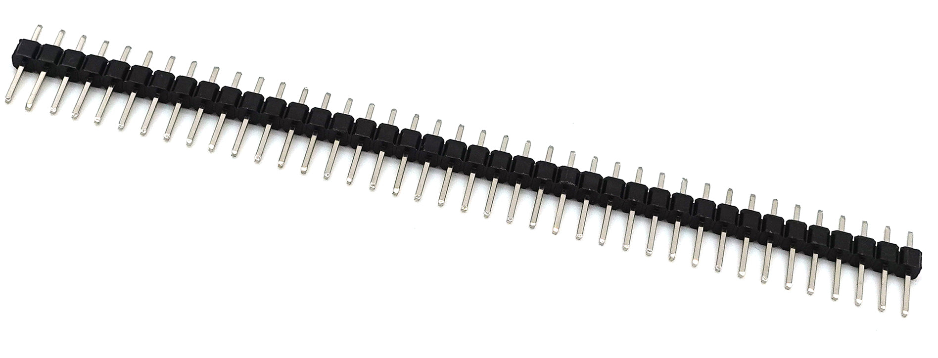
These components generally come in two styles: male headers with exposed metallic pins, and female headers containing sleek internal sockets. They feature a standardized spacing—often exactly 2.54mm apart—which perfectly matches standard breadboards and prototyping gear. Built with durable insulation and conductive brass or bronze contacts, these connectors are rated to safely handle low-voltage signals and moderate currents up to 3 amps.
When you open a new practice kit, you will often find these headers provided in long strips. One of their best features is their customizable nature; you can easily snap or cut them down to the exact number of positions required for your specific board. Once aligned, a small amount of neat soldering permanently secures them to the circuit board, ensuring stable data transmission even during heavy handling.
Section 2: Real-World Use in Arduino Projects
In the wider ecosystem, pin headers are absolutely essential for expanding the capabilities of your development board. Because standard development platform units come with pre-installed female sockets, soldering male headers onto your custom add-on boards or sensors allows them to plug directly together like building blocks.
A classic example is building a custom weather monitor station. By adding these connectors to an external temperature sensor, you can easily plug it into your main board to read data, or swap it out instantly if you decide to upgrade to a different module later on. It keeps your hardware modular, clean, and completely free of messy tangled wires.
Another popular hobby application involves connecting an external display screen, such as a mini LCD or OLED module. Soldering a row of headers onto the display board lets you insert it directly into a prototyping breadboard, making it incredibly simple to link up the power and communication lines. This allows you to focus entirely on writing your software script without worrying about loose, intermittent hardware connections ruining your test run.
See It in the Testudo Kit
Every component in this guide is part of the Testudo soldering practice kit — a hands-on way to learn electronics, soldering, and Arduino coding from the ground up.


