

Section 1: Overview & How It Works
Imagine a water pipe with water rushing through it at full force. If that rush of water hits a delicate valve, it could easily cause damage. To protect the system, you would install a restriction to slow down the flow.

In the world of electronics, electricity behaves a lot like that water, and the component used to slow it down is called a resistor. Its primary job is to provide resistance, safely limiting the flow of electric current through a circuit.
Structurally, a typical thin-film leaded resistor consists of a tiny ceramic core coated with a specialized metal film layer. A precise groove is cut into this film to set the exact amount of electrical resistance required.
The component is wrapped in a protective coating and finished with two metal leads, which are perfect for a soldering practice kit. Because these leads are coated with pure tin, they offer excellent solderability, making them highly reliable when you sit down for some soldering practice.
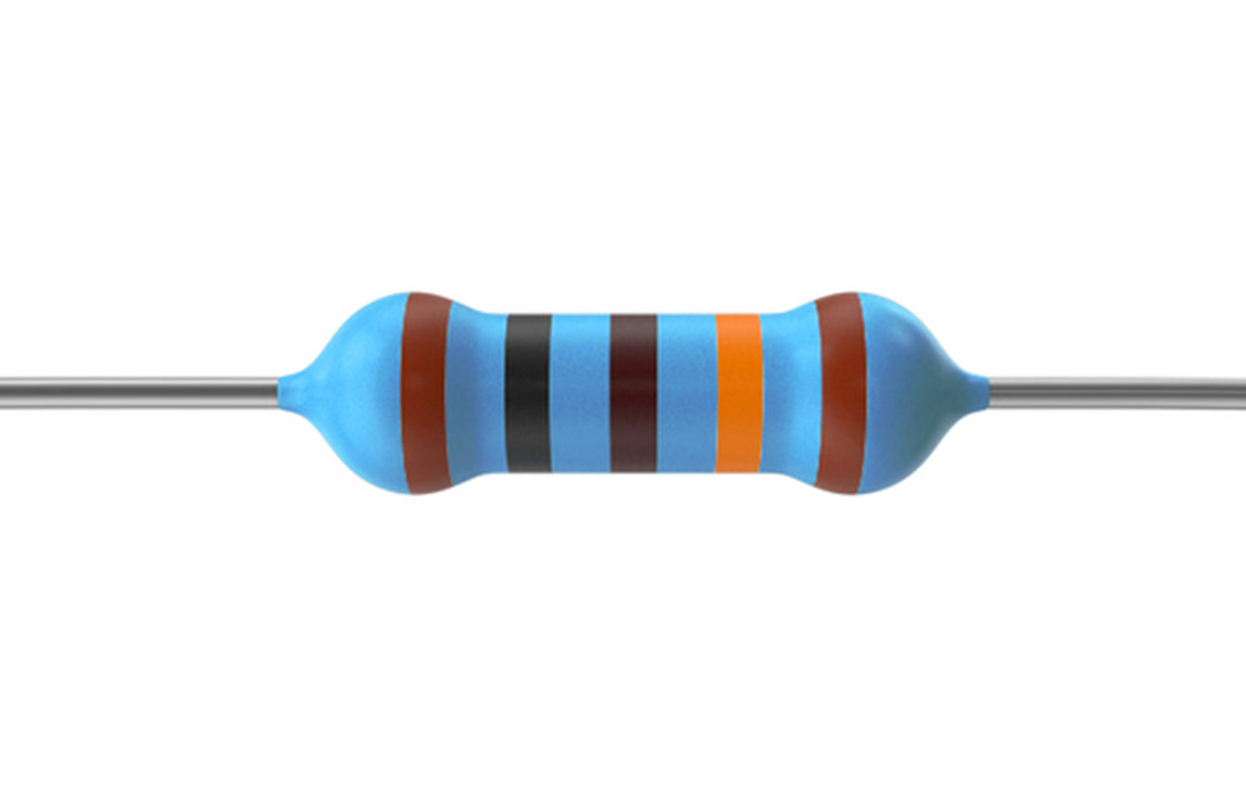
Every resistor is marked with distinct colored bands. These rings tell you its resistance rating and tolerance, allowing you to quickly identify the correct part for your hobby layout.
Section 2: Decoding the Bands (4-Band vs. 5-Band)
Because resistors are so small, printing text numbers on them would be incredibly difficult to read. Instead, the electronics industry uses a standardized system of colored bands to communicate each component's specific values. Depending on the precision required for your project, you will generally work with either 4-band or 5-band resistors.
The colour-band chart below shows exactly what each band represents, so you can decode any resistor on your workbench at a glance.

The difference between the two comes down to how precisely the resistance value is stated:
- 4-Band Resistors: These are the standard components you will find in most general kits. The first two bands represent the primary digits of the resistance value, the third band acts as a multiplier, and the final band indicates the tolerance (how much the actual resistance might vary from its stated value).
- 5-Band Resistors: These are high-precision components. They feature an extra band to provide a third significant digit before the multiplier, followed by the tolerance band. This allows for much tighter, more specific resistance values in sensitive applications.
By understanding how to read these sequences, you can instantly determine the electrical capabilities of any resistor on your workbench.
Section 3: Real-World Use in Arduino Projects
If you are a maker diving into modern electronics, you will find that resistors are absolutely essential. They act as the ultimate safeguard for your boards and peripheral components.
The most common real-world application is current limiting for light-emitting diodes (LEDs). An Arduino digital pin outputs a standard voltage that can easily burn out a basic LED if connected directly. By placing a small resistor between the pin and the LED, you limit the current to a safe level, keeping your indicator light bright and functional without risking permanent hardware damage.
Another classic use is creating a stable environment for input switches, often called pull-up or pull-down configurations. When building an Arduino project with a physical push-button, leaving an input pin disconnected when the button is open creates electrical "noise." A high-value resistor forces the pin to a known state (either ground or 5V) until the button is pressed, ensuring your code reads a clean, accurate signal every single time.
See It in the Testudo Kit
Every component in this guide is part of the Testudo soldering practice kit — a hands-on way to learn electronics, soldering, and Arduino coding from the ground up.


